¶ Linker scripts
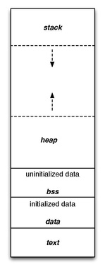
Program code and data is usually split into portions called segments. Program instructions are conventionally put into .code segment, initialized data (e.g. int foo = 1;) is put into .data segment, memory for uninitialized data (e.g. int foo;) is allocated in .bss section. Code placing is controlled by linker scripts and usually looks something like this:
Linker script header defines binary format.
OUTPUT_FORMAT("elf32-littlearm", "elf32-bigarm", "elf32-littlearm")
OUTPUT_ARCH(arm)
Section MEMORY defines chip memory regions. Each memory region is assigned a name (e.g. RAM, ROM, FLASH), access mode (r read, w write, x execute), region origin and size.
MEMORY {
        FLASH	(rx)	: ORIGIN = 0x08000000,	LENGTH = 64k
        RAM	(rwx)	: ORIGIN = 0x20000000,	LENGTH = 20k
}
After that code sections are placed to the specified memory regions.
¶ RAM mode
In the previous project we booted STM32 microcontroller from RAM. This is the most simple mode from the linker scripting perspective. Full linker script is shown below.
OUTPUT_FORMAT("elf32-littlearm", "elf32-bigarm", "elf32-littlearm")
OUTPUT_ARCH(arm)

MEMORY {
        RAM	(rwx)	: ORIGIN = 0x20000000,	LENGTH = 20k
}

_stack_start = 0x20005000;

SECTIONS {
        .isr_vector : {
                KEEP(*(.isr_vector))
                . = ALIGN(4);
        } > RAM
        .text : {
                *(.text)
                . = ALIGN(4);
        } > RAM
        .data : { *(.data) } > RAM
        .bss  : { *(.bss)  } > RAM
}
Here we define only one memory region RAM with size 20k beginning at address 0x2000_0000. These values are obtained from the chip datasheet.
The first section to be placed is .isr_vector. This section contains reset vector and marked KEEP so that linker would not discard it even if these values are not referenced in the code. Note that _stack_start symbol used in the reset vector is defined here so that stack position would be controlled from the linker script.
Line . = ALIGN(4); forces .isr_vector to be 4 byte aligned. All other sections are placed below.
¶ Flash mode
Running programs from RAM is not very practical because data in RAM is not preserved between device power downs. STM32 allows running programs loaded into embedded Flash, which has its nuances. Due to its nature, Flash memory may only be written to in blocks. Before write, Flash block must be erased. Therefore, its not possible (without much overhead) to put mutable data onto the Flash memory.
Initial values of user data may be stored on the Flash but it needs to be relocated to RAM to be mutable.
Usually user data is split into immutable (read-only)
.rodatasection and mutable.datasection.
To distinguish between initial and final data position linker uses special terms. Load memory address (LMA) is the address of memory region upon loading. Initially, user data will be located at LMA. Virtual memory address (VMA) is the address where user data is expected to be by the program. In case of relocatable .data section, its contents reside in Flash (LMA) but expected by the rest of the code the be in RAM (VMA). This relocation is one of the microcontroller initialization steps.
OUTPUT_FORMAT("elf32-littlearm", "elf32-bigarm", "elf32-littlearm")
OUTPUT_ARCH(arm)

MEMORY {
        FLASH	(rx)	: ORIGIN = 0x08000000,	LENGTH = 64k
        RAM	(rwx)	: ORIGIN = 0x20000000,	LENGTH = 20k
}

_stack_start = 0x20005000;
_data_lma = LOADADDR(.data);

SECTIONS {
        .isr_vector : {
                KEEP(*(.isr_vector))
                . = ALIGN(4);
        } > FLASH
        .text : {
                *(.text)
                . = ALIGN(4);
        } > FLASH
        .data : {
                _data_vma = .;
                *(.data)
                _data_evma = .;
        } > RAM AT>FLASH
        .bss : { *(.bss)  } > RAM
}
In the snipped above .data section is placed in RAM with its initial location specified by AT>FLASH command. For the data relocation we need information about .data section LMA, VMA and its size. We obtain LMA address using _data_lma = LOADADDR(.data); directive and assign it to _data_lma symbol. VMA of section .data beginning and end are obtained by wrapping *(.data) directive in symbol = .; commands. In the code above .data beginning and end addresses are assigned to _data_vma and _data_evma symbols. These three values are enough to relocate .data section into RAM.
Relocation itself is implemented as a simple loop.
        ldr r0, = _data_vma
        ldr r1, = _data_evma
        ldr r2, = _data_lma
0:
        ldr ip, [r2]
        str ip, [r0]
        add r0, r0, #4
        add r2, r2, #4
        cmp r1, r0
        bgt 0b
¶ Exercises
- Place
.bsssection in RAM above stack.
¶ References
Picture Memory layout was taken from https://en.wikipedia.org/wiki/Data_segment
https://sourceware.org/binutils/docs-2.27/ld/index.html